K - CONCRETE VESSELS

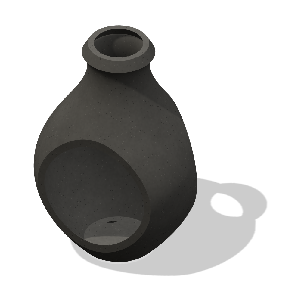
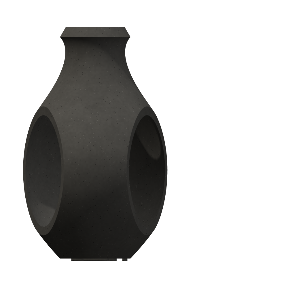
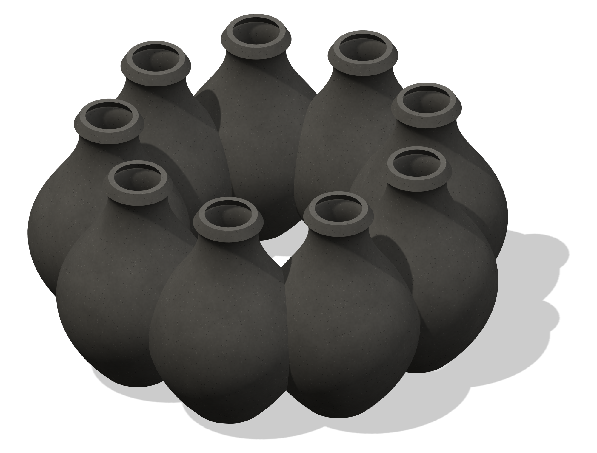
K is a set of nine black concrete planters that fit together into a ring about six feet across. Each vessel is roughly 35” tall and 24” wide, cast in glass-fiber-reinforced concrete (GFRC) with black pigment mixed all the way through, so a chip never shows a different color underneath. The sides are left open so soil can be packed in and plants can grow out through the gaps as well as the top.
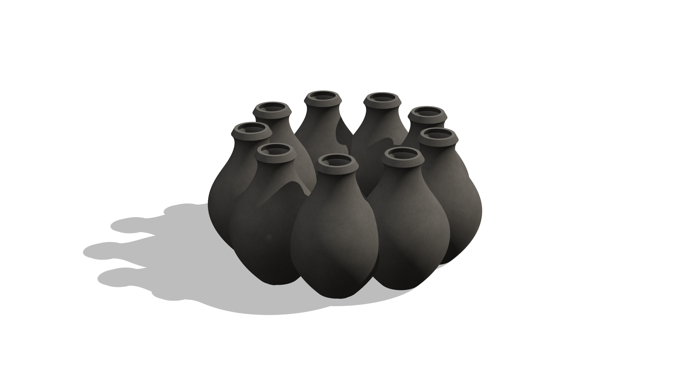
The Vessel

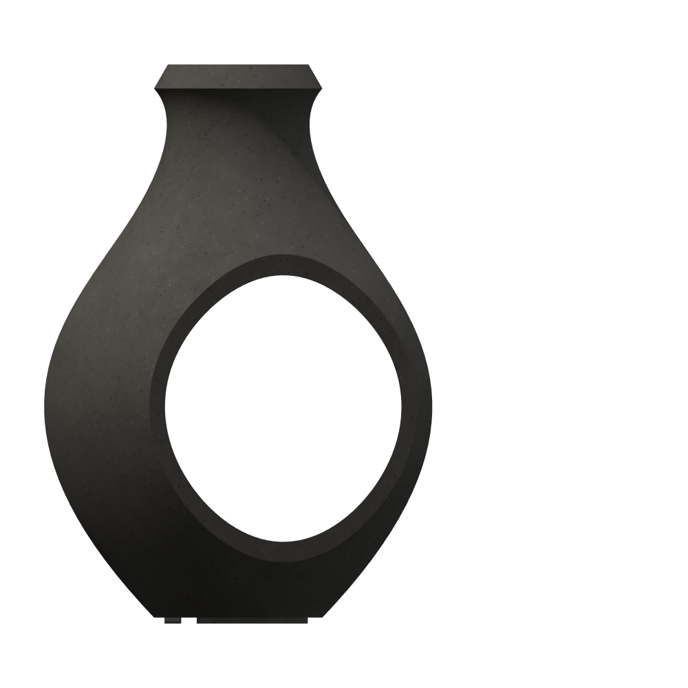
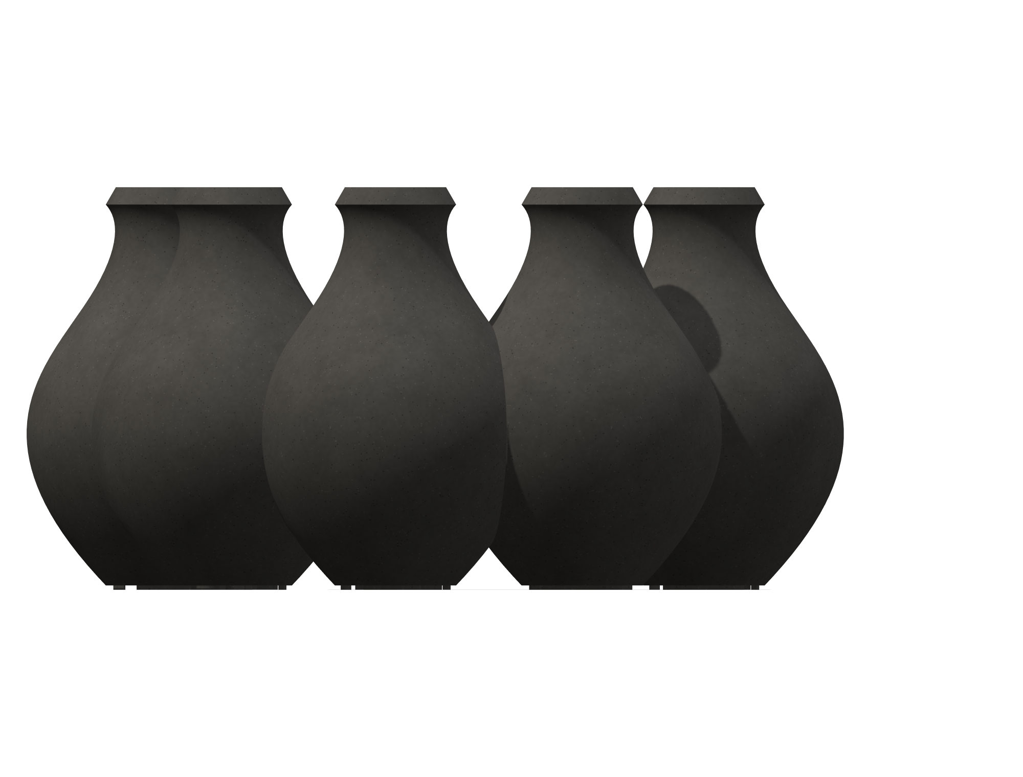
One vessel: 35” tall, 24” wide, with 3/4” walls of black GFRC that is the same color all the way through. The open sides change its outline as it turns, so it never reads the same way twice.

THE MOLD

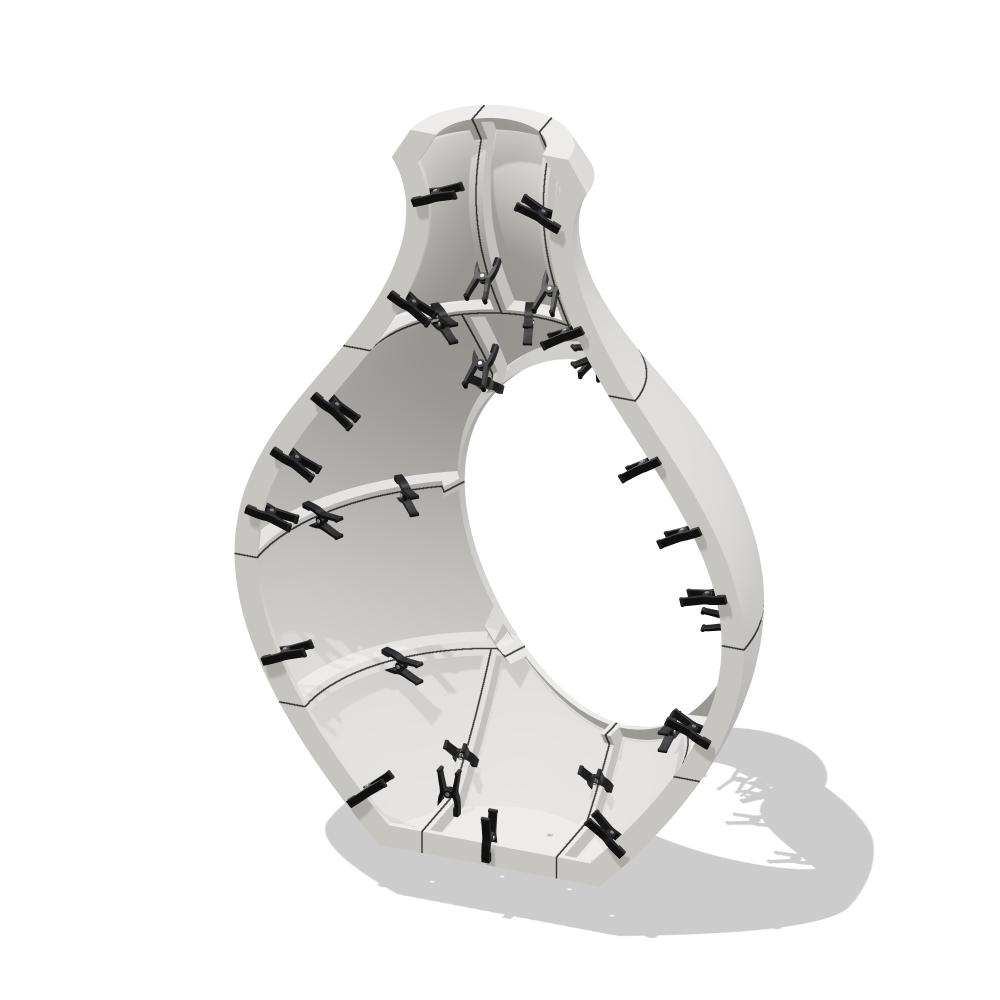
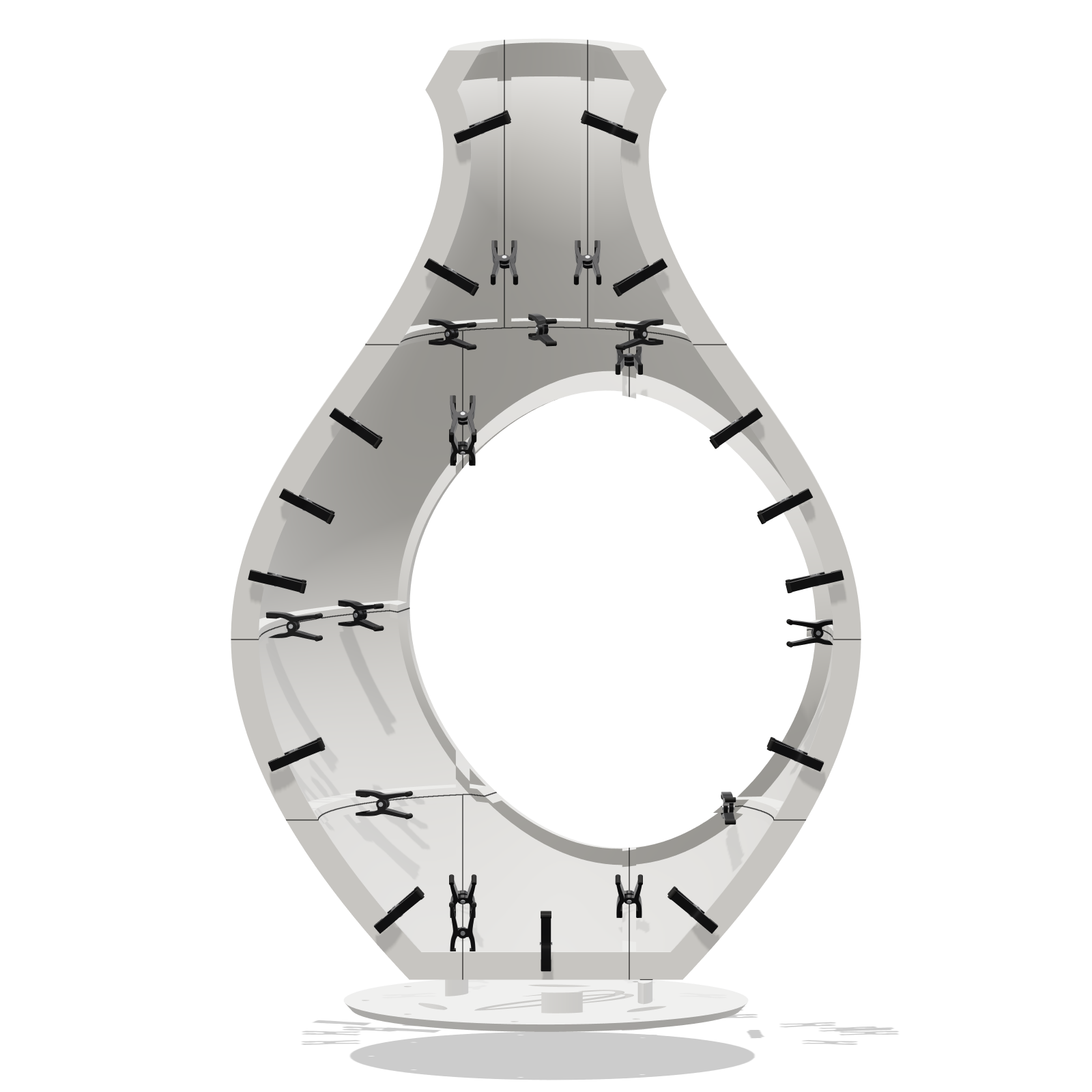
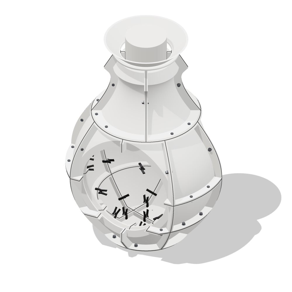
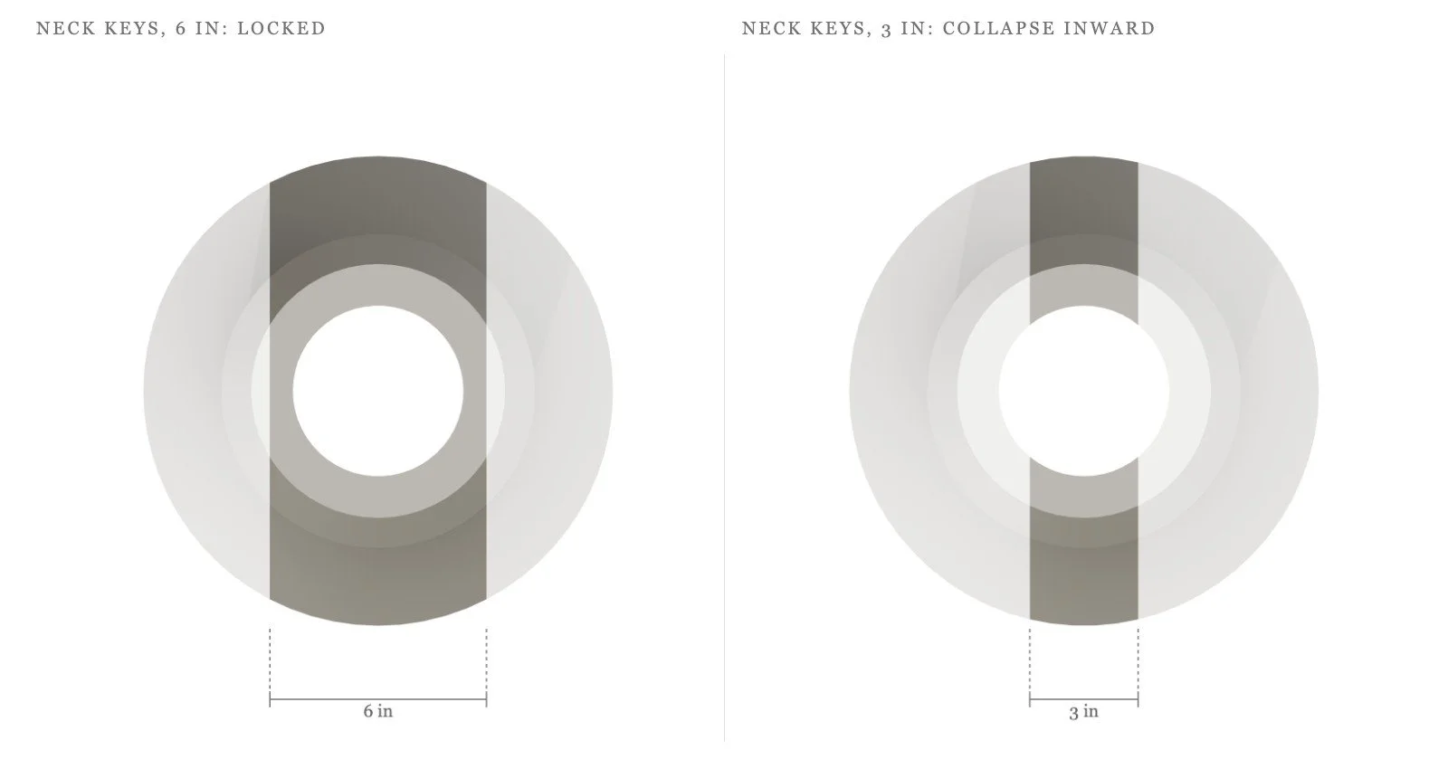
The pot is cast in a 3D-printed PETG mold with an outside and an inside. The outside is 29 pieces bolted together in bands, each with its own pull direction. The inside is a 22-piece hollow core that forms the interior, cut open at the two side openings. Concrete goes in through a funnel at the top, and the riser above the rim catches the excess, which gets struck off flush. To demold, the funnel and core cap lift off, the bolts come out (the mold stands on blocks so the ones under the base plate can drop out), the outside comes off top band first, and the clamps are taken out by hand, the few in the neck from the top and the rest through the side openings. Then the core collapses: the key pieces pull inward first, and every core piece leaves through one of the two side openings. The neck keys are cut narrower than the rest (3” instead of 6”) so the two halves of the narrow neck can pull in past each other under the flared lip. Last, the pot lifts off the base plate, which leaves the logo ribs printed on the bottom.

The Clamps

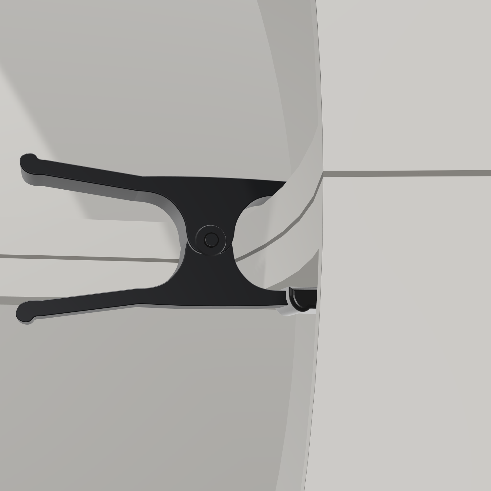
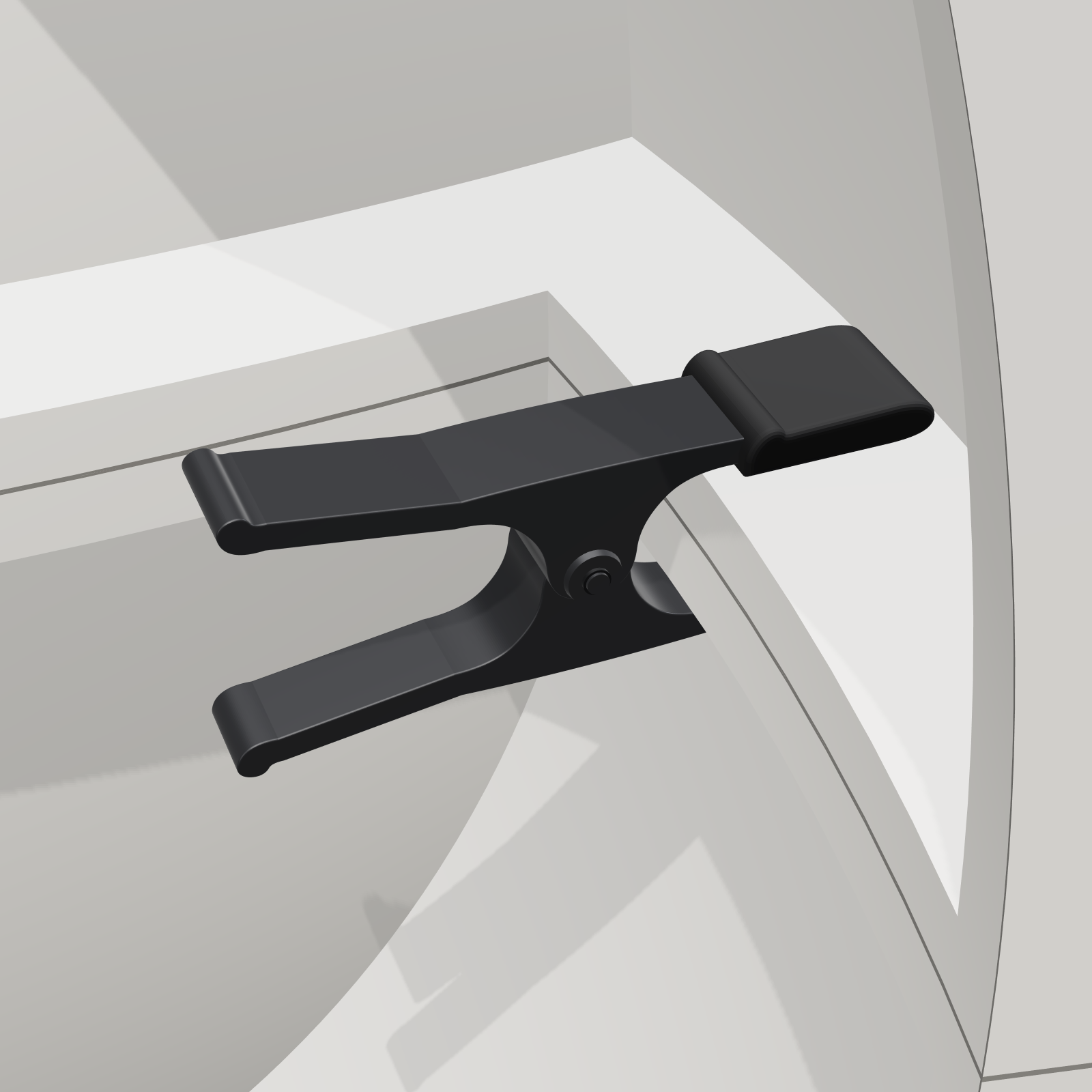
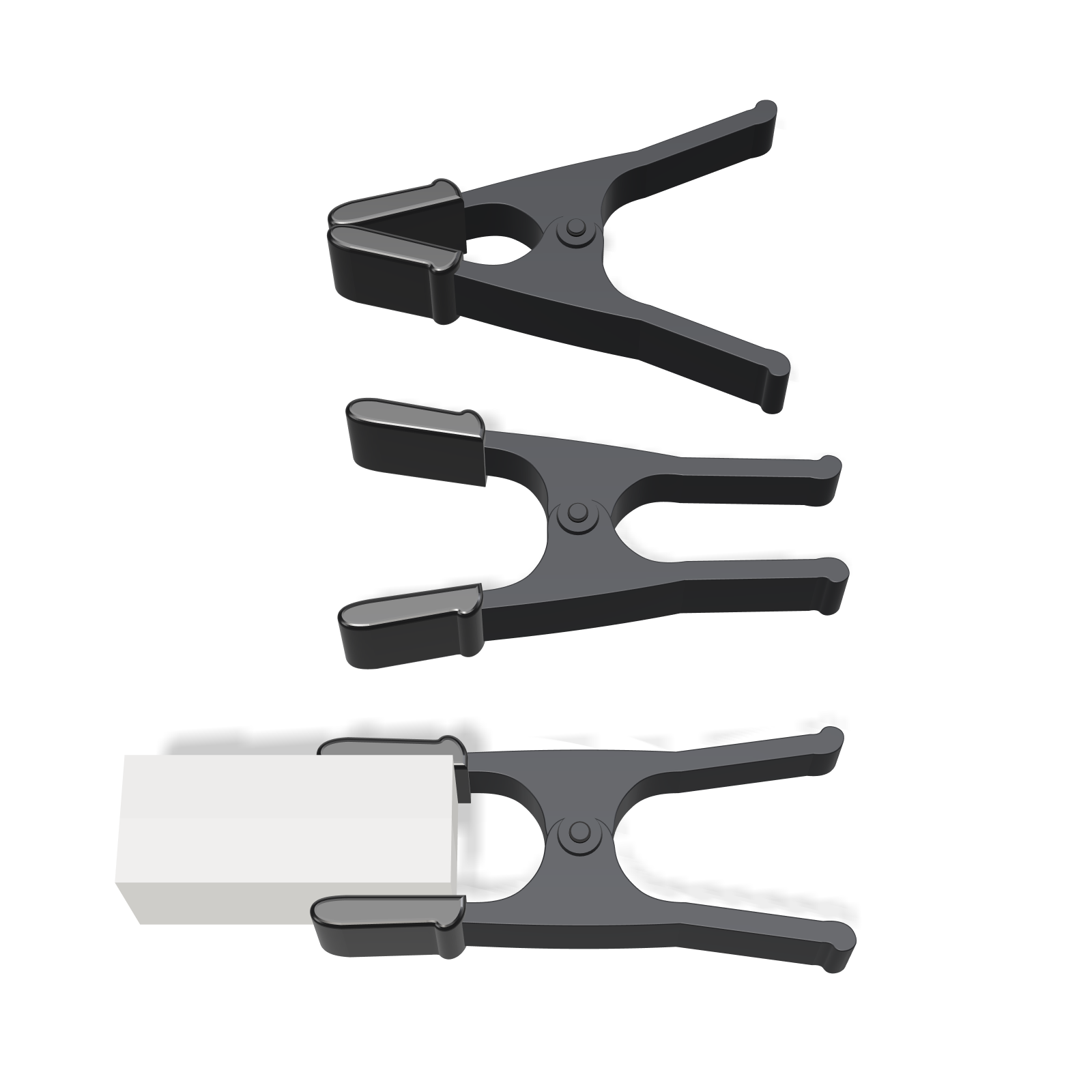
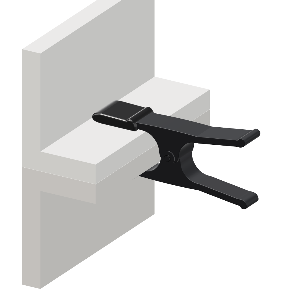
The core assembles on the bench. Two key pieces lock each band, and 2” spring clamps bite the flange pairs from the inside, where there is no room for a wrench. Squeezing the handles opens the rubber jaws. Let go and they bite down on both flanges while the handles flare back out. The outer mold bolts together with 1/4” stainless bolts. The assembled core lowers into the open mold before the shoulder band goes on, boards across the side openings register it, and sandbags brace the shell for the pour. Demolding, the clamps pop off through the side holes and each piece slides inward and out.
Assembly

The mold goes together from the bottom up on the base plate, which stands on three 1½” blocks. The lower band goes on first, then the belly, and each piece is bolted to its neighbors through the flanges with 1/4”-20 stainless bolts, washers, lock washers, and nuts. The core is stacked and clamped together along its seams on the bench, with the clamps going on through the side openings and the neck, and then lowered in as one unit. The shoulder and neck bands close over it, then the core cap and the funnel go on top, and it’s ready to pour.

The Pour

GFRC goes in through the funnel at the top and runs down between the core and the outer mold. It fills from the bottom up, wraps around the side opening, and keeps rising until it comes up into the riser above the rim. The riser holds the excess, which gets struck off flush. Here the front half of the mold is cut away and the core is drawn see-through so you can watch the fill.

THE RING

Nine separate pots slide together into one ring about six feet across. Nothing is glued, so the ring can be pulled apart, moved, rearranged and replanted. On their own each pot tips at about 8 degrees; pushed together they brace each other.
Process
Scaling for concrete. The original design had 0.5" walls, too thin for concrete. I took the walls to 0.75" and scaled the whole design 1.5x with them so the proportions stayed the same.
Getting it out of a mold. The shape is full of undercuts and closes in on itself, so it needs a mold on the inside as well as the outside. The outside is 29 3D-printed PETG pieces bolted together in bands, each with its own pull direction. The inside is a 22-piece hollow core whose pieces slide toward the middle and come out through the side openings.
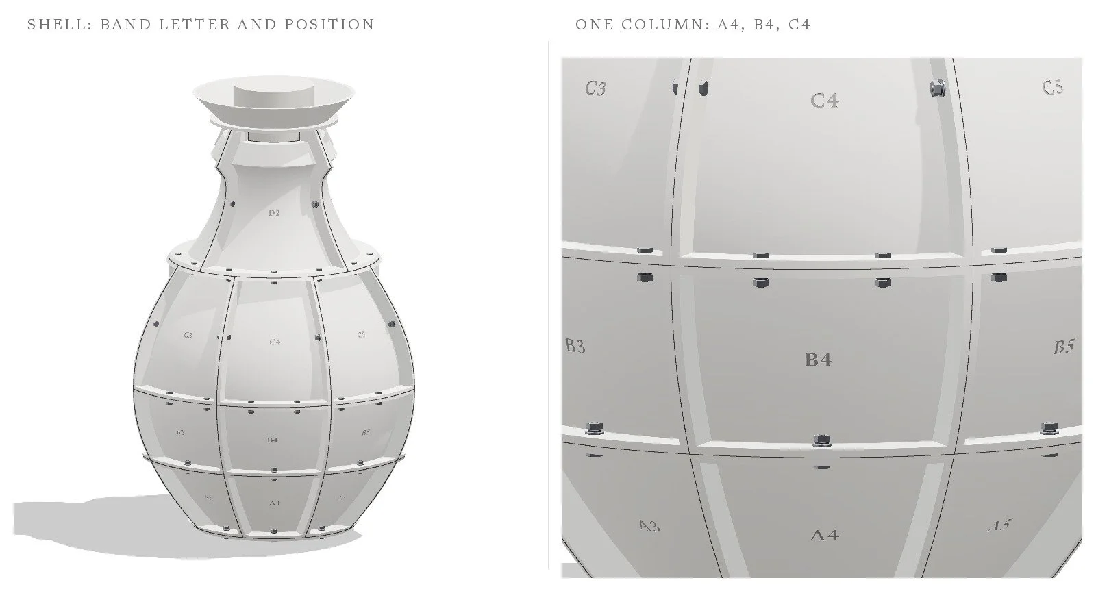
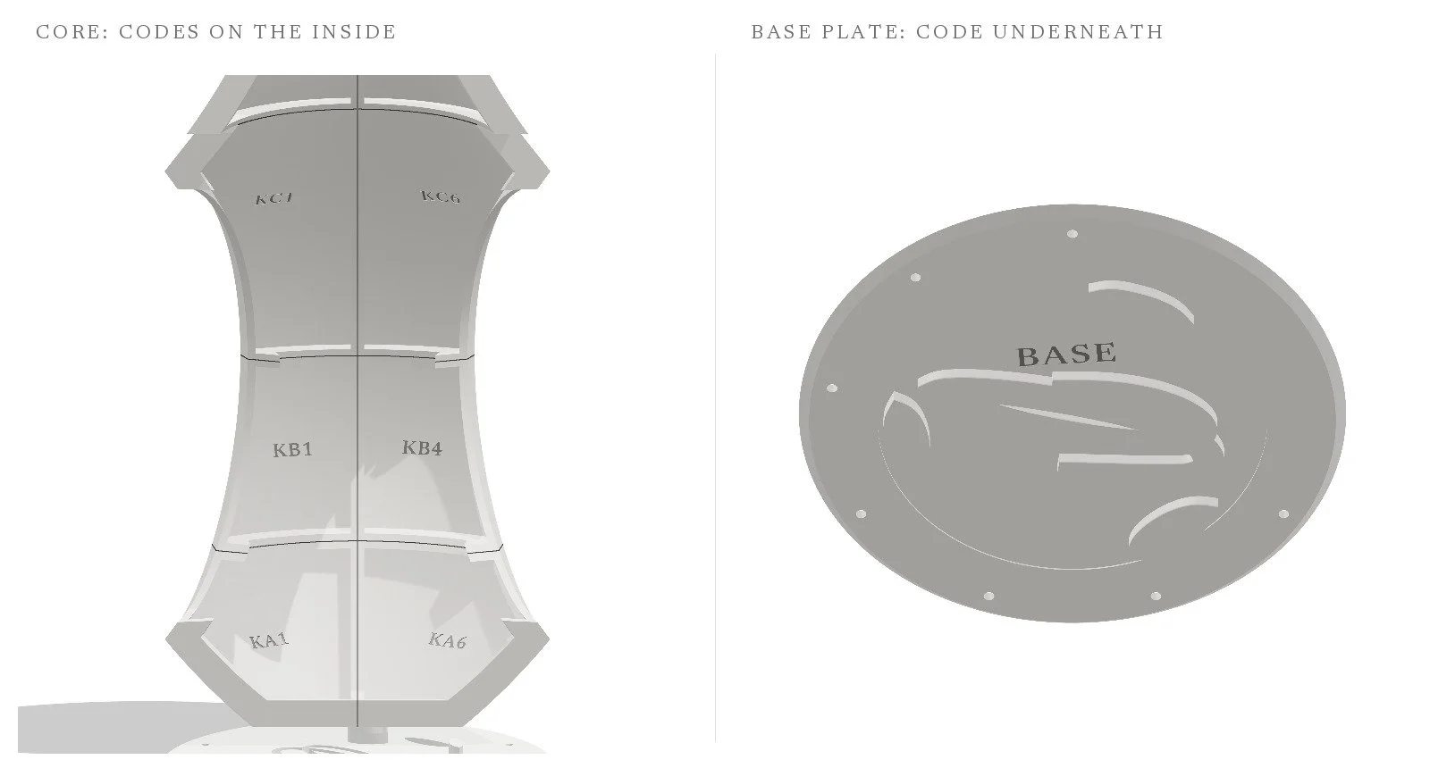
Part codes. Every printed piece has its code cut into it, set in Newsreader, the typeface of this site. Shell pieces get a band letter, A at the bottom to D at the neck, and a number counting around the vessel, so A4, B4 and C4 stack in one column. Core pieces get a K in front (KA1 to KD6), and the funnel, cap and base plate are F, CAP and BASE. The codes are 1/32" deep and only on faces that never touch concrete: the outside of the shell, the inside of the core and the underside of the base, so they never show on a pot.
The assembled mold with a part code on each shell piece, and a close-up of one column of codes: A4, B4, C4
Part codes on the inside of the core, and BASE on the underside of the base plate
The pour. Black GFRC goes in through a funnel at the top and down into the rim. A 1.5" riser above the rim takes the excess, which gets struck off flush before it sets, and small vents in the core floor show when the bottom has filled.
Tipping over. Each vessel stands on a narrow footprint with its center of mass about 15.7" up, so a single pot tips at roughly 8 degrees. In the ring they brace each other. I kept them as separate pieces instead of gluing them into one 740 lb object, so they can be moved, rearranged and replanted. Each one is about 85 lb.
The base. The ribs on the underside are my logo, so lifting a pot off sand or soil leaves the logo printed behind. The sharp-oval negative shapes of the logo became the feet and the drain slots.
Weather. The concrete is sealed with a penetrating sealer so water doesn't soak in and crack it through freeze-thaw.
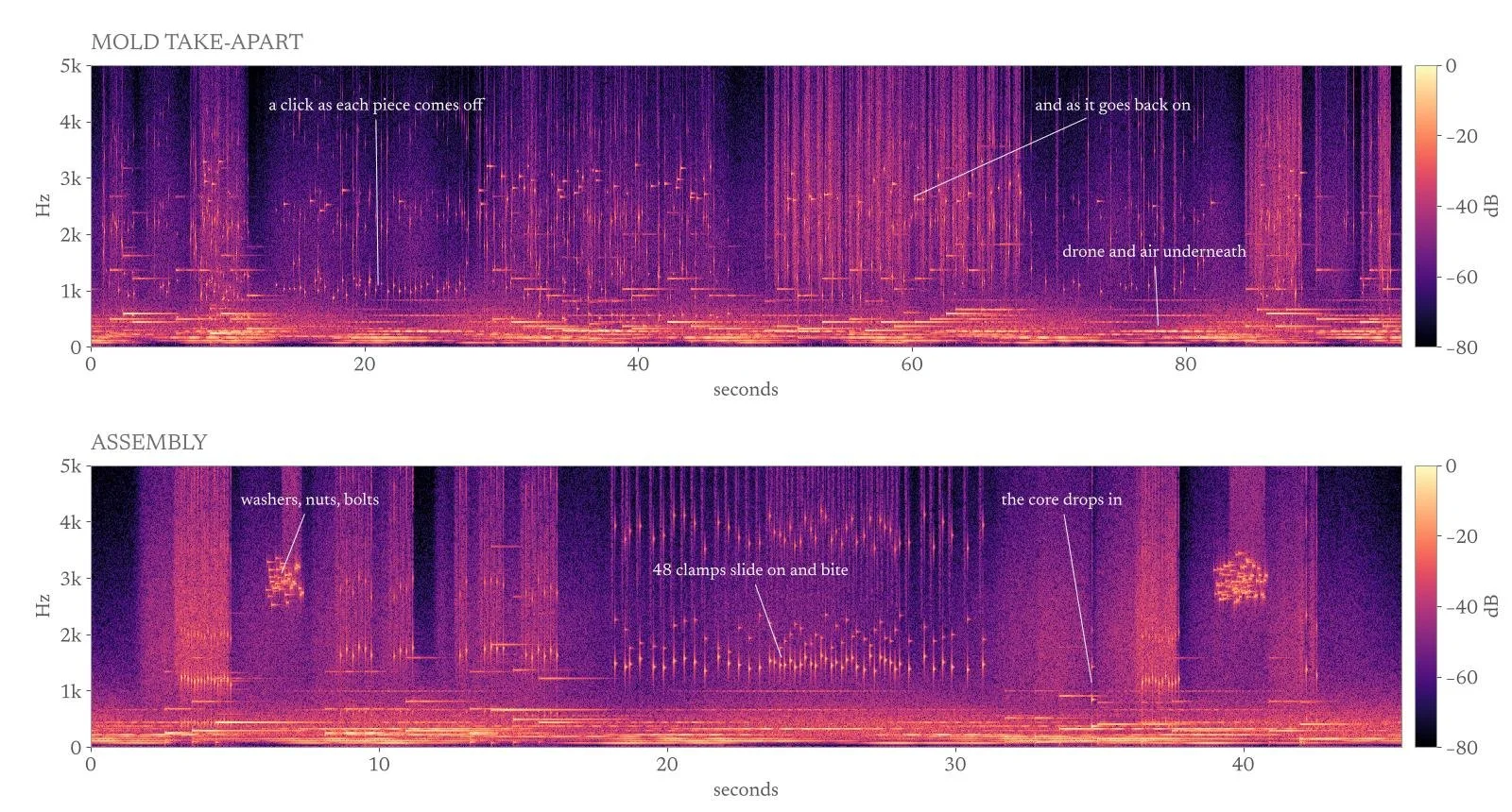
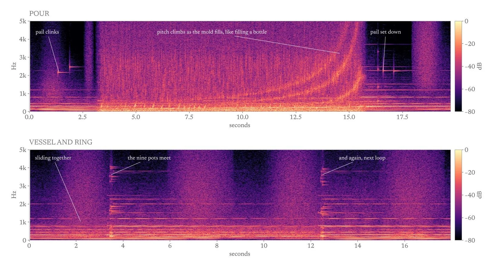
Sound. The vertical cuts of these animations made for Instagram have sound, and none of it is recorded. Every track is generated and timed to the animation itself: a low drone and air underneath, struck-stone tones when the big pieces land, and quiet clicks on the frame each piece seats, each clamp bites and each bolt turns. The pour is modeled as liquid filling a closed column, so its pitch climbs as the mold fills, the way a bottle does, and the nine pots knock when they meet. I checked every mix as a spectrogram: time in seconds across, frequency in Hz up, and color for loudness in dB below the loudest moment.
Spectrograms of the mold take-apart and assembly soundtracks, with the clicks of pieces, clamps and bolts marked
Spectrograms of the pour, where the pitch climbs as the mold fills, and of the vessel and ring, where the nine pots meet
Checks and iterations
Before ordering prints, every step of building and demolding the mold was checked in CAD: each piece moved along its path and tested for collisions, every bolt checked for wrench room, and every clamp checked for reach. These are some of the problems that turned up and how they were fixed.
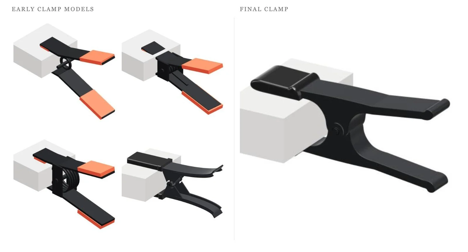
Early spring clamp models next to the final clamp
Clamp model. The 2" spring clamps took nine rounds to model: a spring floating off the hinge, arms passing through the flange, a coil jammed between the jaws, handles too blocky. The final version bites both flanges with rubber tips while the handles flare back out.
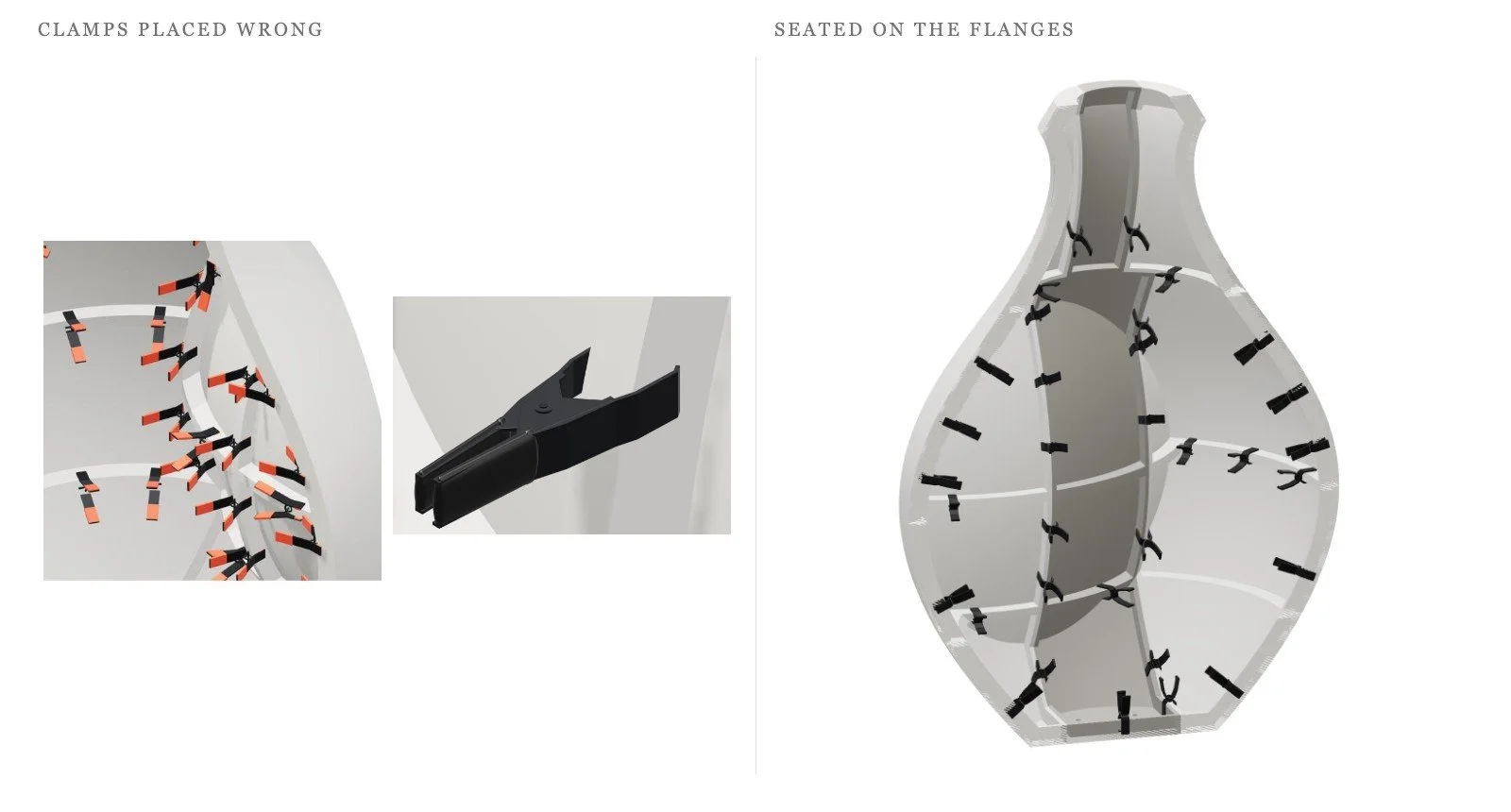
Clamps placed wrong in an early core cutaway, and the final clamps seated on the core flanges
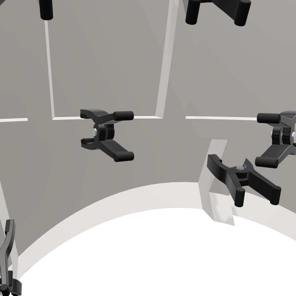
Clamp placement. Early layouts had clamps scattered at the wrong spacing and some facing backwards, with the handles pointing into the core wall. Every clamp now sits on its flange pair inside the core with the handles pointing into the open middle, and nothing passes through a wall.
Top view of the neck keys at 6 inches and at 3 inches
Neck keys. With 6" key strips all the way up, the two neck keys met in a closed ring under the flared lip, so they had nowhere to go. Cutting them to 3" in the neck band leaves a gap between them, so each one slides inward and out.
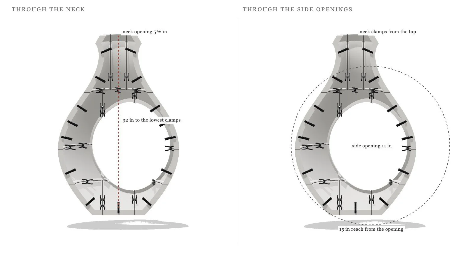
Reach to the clamps through the neck compared with through the side openings
Getting the clamps in and out. The neck opening is only 5½" across and the lowest clamps sit 32" below it, too far to reach. The two side openings are 11" across and every clamp below the neck is within 15" of one, so those go on and come off by hand through the sides. The few clamps in the neck are reached from the top.
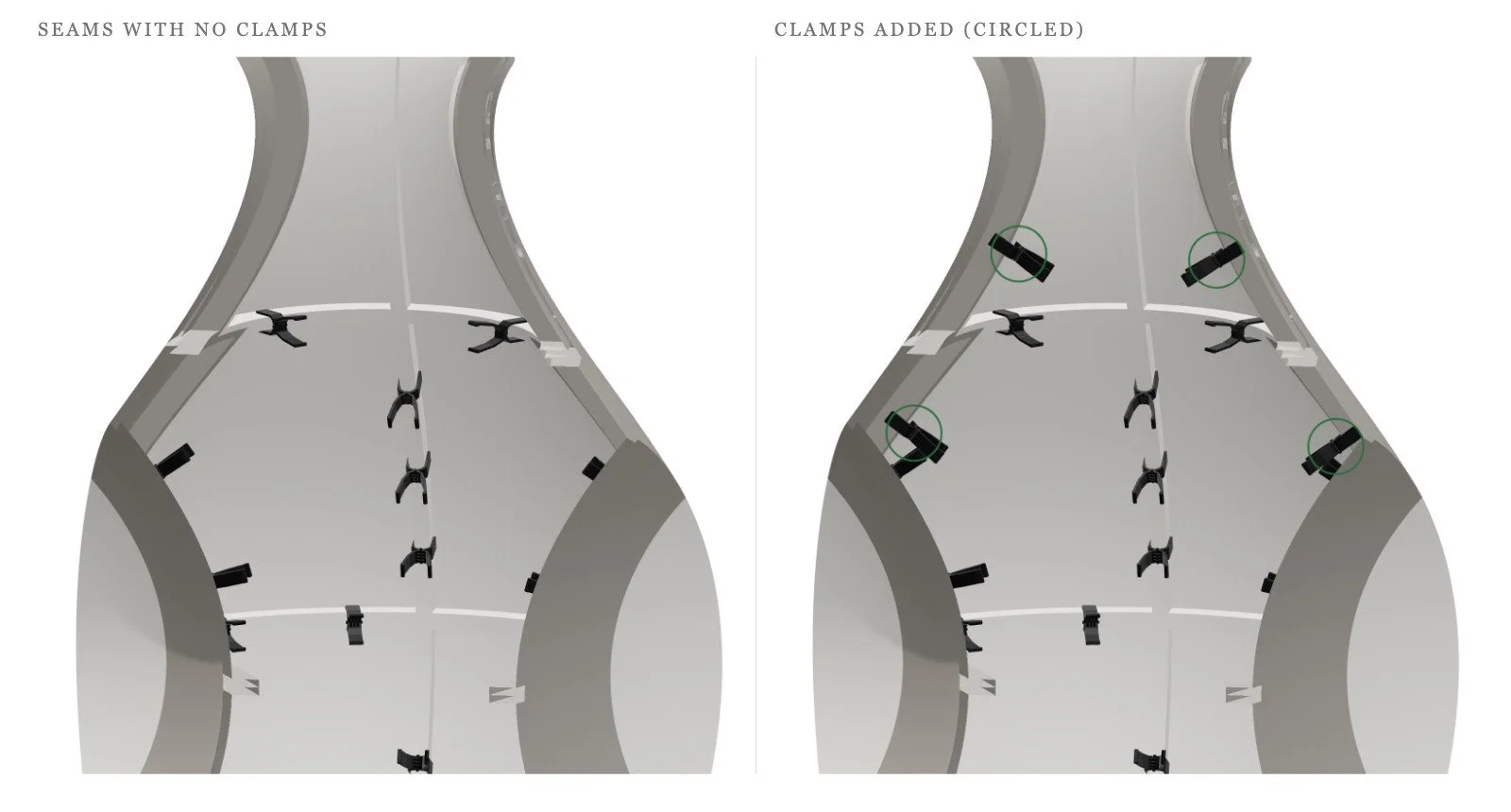
Core seams without clamps, and the same seams with the added clamps circled
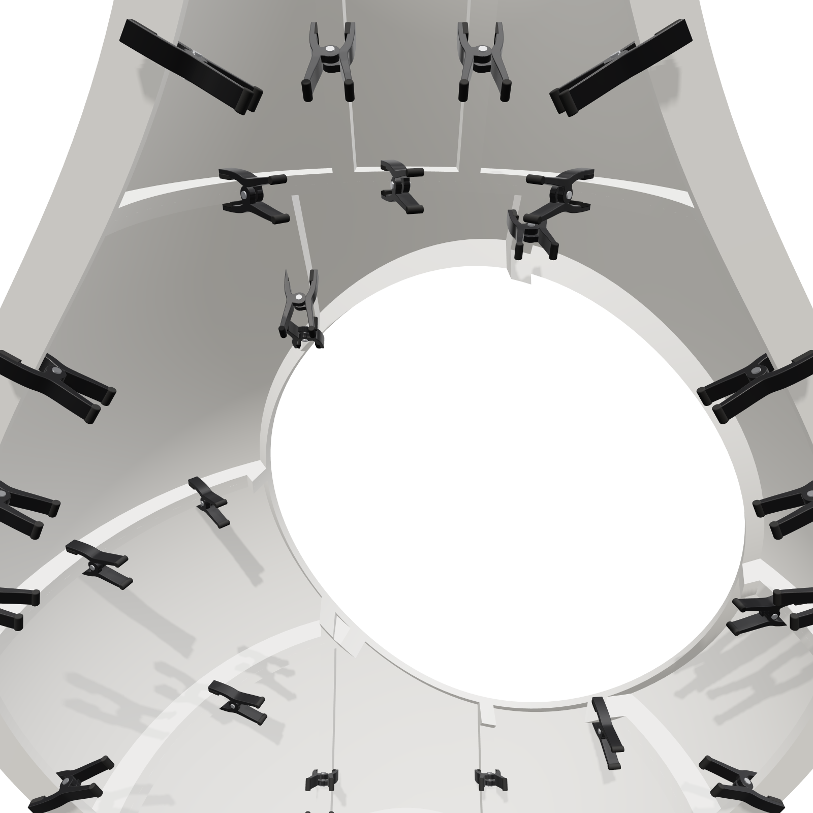
Clamp count. On one side of the core, the key seams through the neck and shoulder had no clamps, and the lower seam had a wide gap. Six more clamps close them up.
Bolts. All 41 bolt joints were checked for room to get a wrench on. Each takes a 1/4"-20 x 1" bolt with a flat washer and lock washer under the nut. The nine nuts under the shoulder flange sit in a tight pocket and need an open-end wrench from the outside, and the bolts through the base plate go in head-down, so the mold stands on 1½" blocks while it is bolted and unbolted. The take-apart animation leaves the blocks out and floats the base plate a few millimeters off the floor, so its shadow still reads.
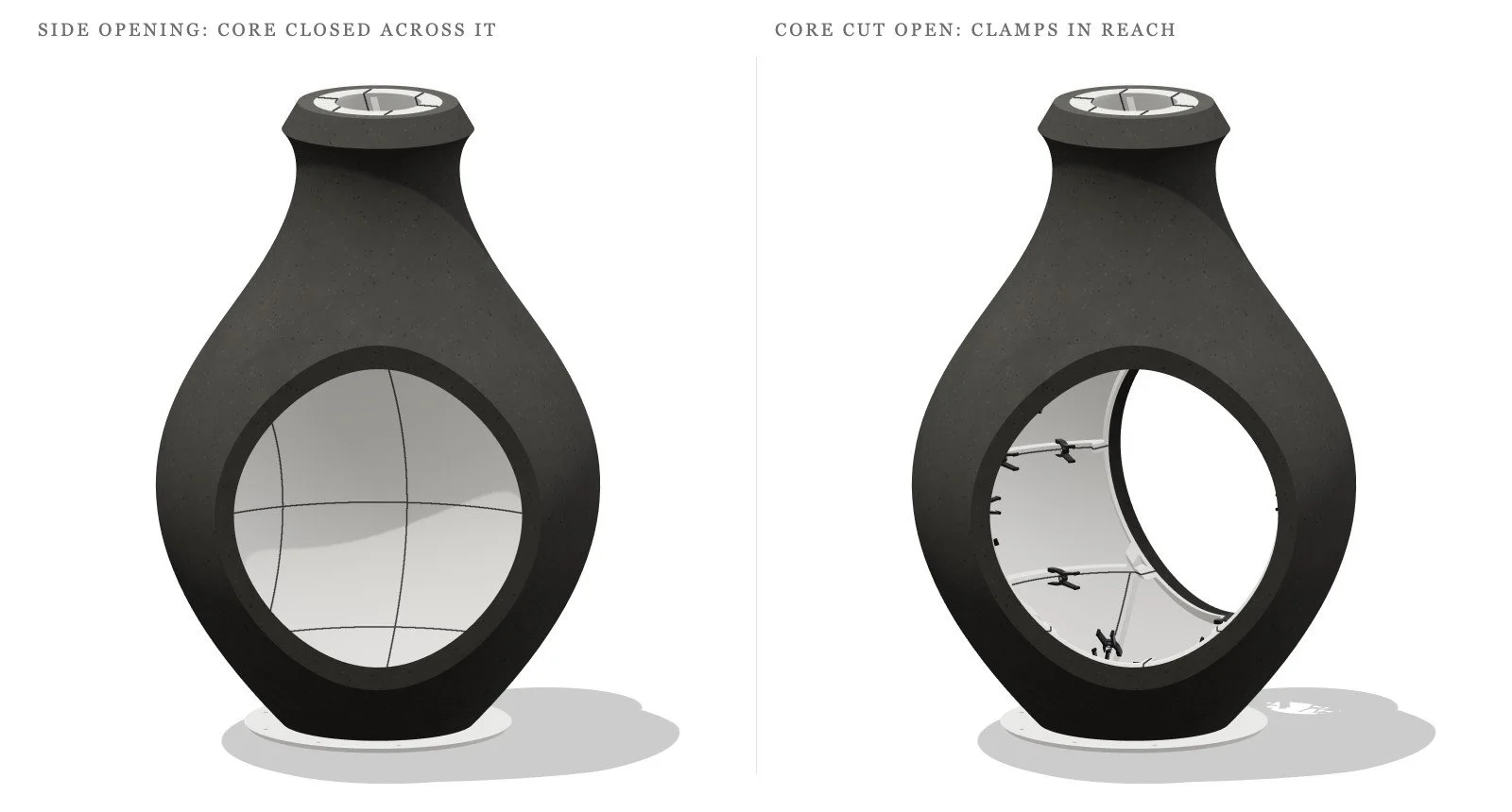
A side opening with the old core closed across it, and the same opening after the core was cut open, with the clamps visible inside
Closed core. A render through a side opening showed the inner core closed across it. The core was shelled from the inside of the pot, so at each side opening it formed a shallow dish, and the clamps behind it couldn't be reached. Both openings are now cut through the core, and two small leftover pieces were merged into their neighbors, which leaves 22 core pieces. Clamps on flanges that were cut away came off and new ones went on the new edges, 48 in all.
Core seams marked in red where the old collision check reported false hits, and the same core with none under the new check
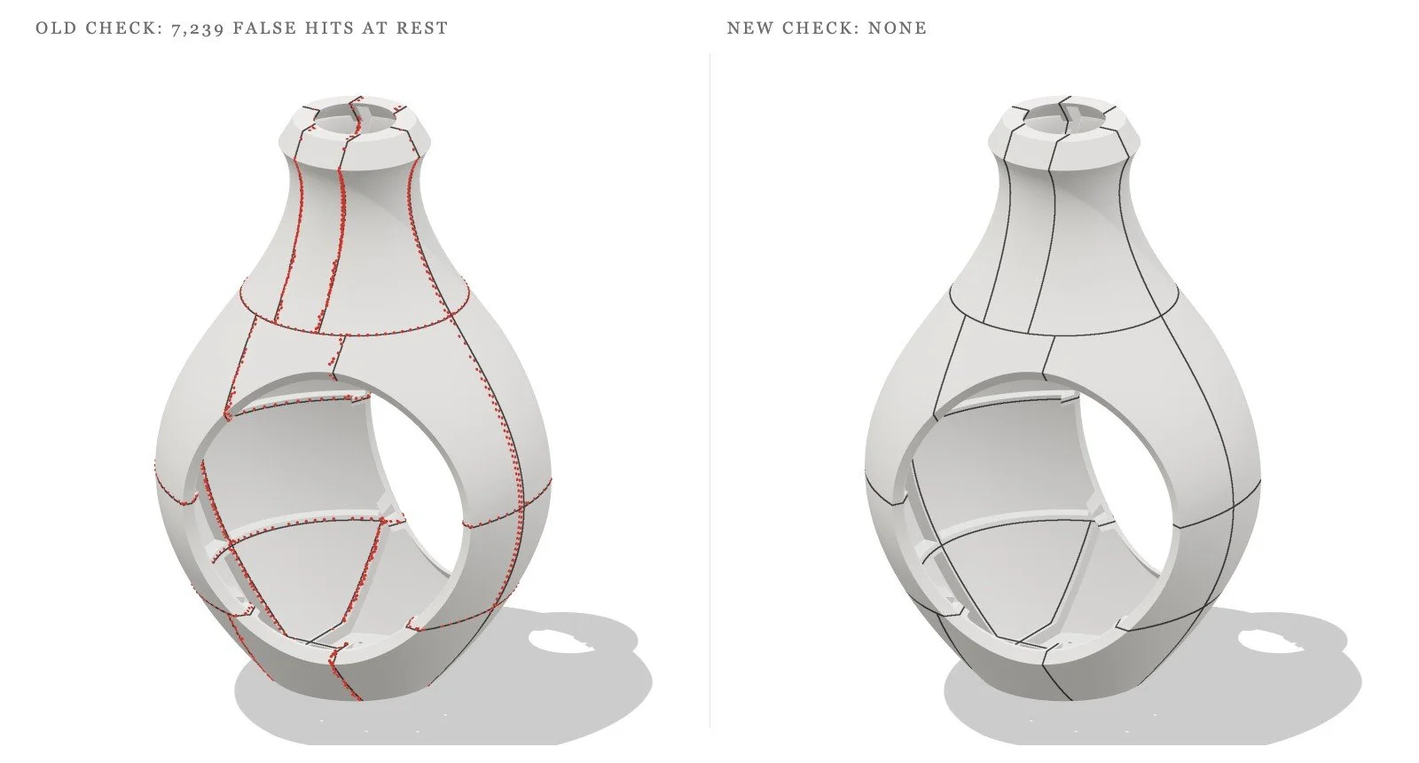
False collisions. The collision check shrinks every part by 0.8 mm before testing, so surfaces that only touch don't count. The first version moved each face in along its own direction, which left the edges where two core pieces meet still touching, and it reported 7,239 hits between pieces that hadn't moved. Pulling each corner in along the average of its faces opens those edges too, so the count at rest dropped to zero, and every clamp and core path was checked again. The demold animation uses the same check: each part's move is tested against everything already moving, and it waits until its way is clear.
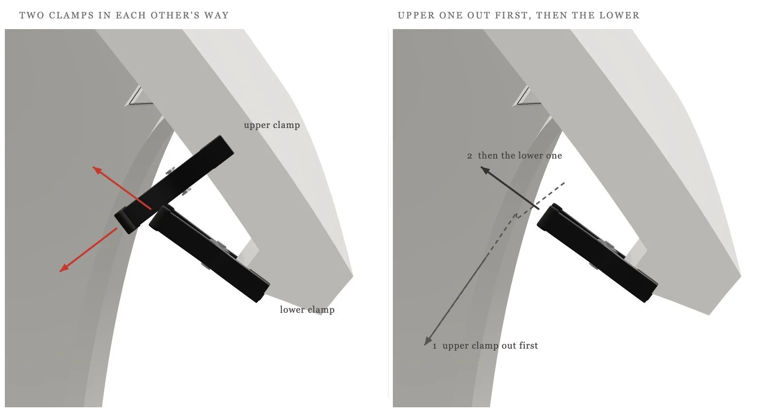
Two clamps in a V whose slide-off directions run into each other, and the new order with the upper clamp out first
Clamps in each other's way. Two pairs of clamps near the side openings sit in a V with their handles almost touching, and each one slides off toward the other. The lower clamp couldn't move without hitting the upper one, and the upper one's way out ran into the lower. Taking the upper clamp out first, on a new path around the lower one, frees both.
Process photos (coming soon)
Photo: printed mold pieces
Photo: mold bolted together
Photo: mixing black GFRC
Photo: inner core assembled
Photo: pouring through the funnel
Photo: demolding
Photo: logo base / sand imprint
Photo: sealing
Photo: soil + planting